
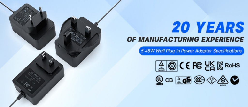
A power adapter is an essential external power supply device for all types of electronic equipment. Its core function is to convert household and industrial alternating current (AC) mains power into stable, safe low-voltage direct current (DC) that electronic devices can recognize and use normally. Contrary to the common misconception of being a simple “voltage reduction device”, a standard commercial power adapter is a high-precision power conversion system integrating filtering, rectification, high-frequency conversion, isolated step-down, closed-loop voltage regulation, and multi-level safety protection.
More than 95% of external power adapters circulating in the global market adopt the flyback high-frequency switching power supply architecture, which has completely replaced traditional linear transformers with bulky size and low efficiency. This article comprehensively explains the complete working principle, core circuit operation logic, voltage regulation mechanism, and protection principle of power adapters.
(1) Overall Working Process of Power Adapters
The power conversion link of a standard switching power adapter is well-structured and interconnected. The complete workflow is divided into six core stages, which constitute the universal standard logic of industrial AC-DC power conversion:
AC Mains Input → EMI Filtering → High-Voltage Bridge Rectification → PWM High-Frequency Power Conversion → Isolated Transformer Step-Down → Secondary Rectification & Filtering + Closed-Loop Voltage Stabilization Output
1.1 AC Input and EMI Filter Circuit
After the mains power enters the adapter port, it will not be directly transmitted to the step-down circuit. Instead, it first passes through the front-end protection and filter circuit for impurity removal and safety protection, serving as the first barrier for stable power operation and international safety compliance. This module consists of a fuse, NTC thermistor, common-mode inductor, X capacitor, and Y capacitor, forming a Pi-type filter network.
The fuse acts as the core safety component. It blows immediately to cut off the power loop in case of circuit short circuit or overload, preventing equipment burnout and fire hazards. The NTC thermistor mainly suppresses the inrush current generated by high-voltage capacitor charging during power-on, relieving instantaneous current impact and protecting precision rectifier components at the rear stage.
The EMI filter network provides bidirectional anti-interference performance. On the one hand, it filters lightning pulses, electrical switching noise, and industrial high-frequency interference from the mains to purify input power. On the other hand, it blocks high-frequency electromagnetic noise generated by the adapter’s internal switching operation from flowing back to the public grid. It fully meets global EMC certification standards such as CE, FCC, and UKCA, avoiding interference with the normal operation of surrounding electronic devices.
1.2 Bridge Rectification and High-Voltage Smoothing Filtering
The purified alternating current is sent to a bridge rectifier circuit composed of four high-speed diodes. Utilizing the unidirectional conductivity of diodes, the bridge rectifier converts AC power with periodically changing current directions into single-way pulsating DC power.
The pulsating DC power at this stage has extreme voltage fluctuations and unstable waveforms, making it unavailable for rear-stage circuits. Therefore, high-voltage electrolytic capacitors are used for energy storage and waveform smoothing. Under standard household mains input, a stable high-voltage DC bus voltage of approximately 310V is generated, providing continuous and steady high-voltage power for subsequent high-frequency conversion circuits.
Medium and high-power industrial and commercial adapters above 50W are additionally equipped with a PFC (Power Factor Correction) circuit, which corrects the input current waveform, significantly reduces grid harmonic loss, improves power utilization, and complies with international energy-saving and grid protection regulations. Small low-power adapters usually omit this module to simplify structure and control costs.
1.3 PWM High-Frequency Switching Conversion (Core Control Unit)
This is the most essential difference between switching power adapters and traditional linear power supplies, and the key reason for the compact size and high efficiency of modern adapters. After the high-voltage DC bus voltage enters the core power conversion module, it is intelligently controlled by a PWM (Pulse Width Modulation) chip — the “brain” of the adapter — which outputs high-frequency pulse driving signals of tens of thousands of hertz.
Driven by the pulse signals, the MOSFET power switch conducts and cuts off rapidly to realize high-frequency cutting of high-voltage DC power. When the MOSFET is on, current flows into the primary winding of the high-frequency transformer, the magnetic core stores magnetic field energy, and the secondary circuit diode is cut off with no energy output. When the MOSFET is off, the primary current is instantly disconnected, the magnetic core releases stored magnetic energy, and the secondary winding induces low-voltage high-frequency alternating current.
This high-frequency switching mode converts steady high-voltage DC power into high-frequency pulse power, greatly improving power conversion efficiency while minimizing the size and weight of the transformer, eliminating the bulkiness and low efficiency pain points of traditional power frequency transformers.
1.4 High-Frequency Isolated Transformer Step-Down
The high-frequency pulse voltage is transmitted to a dedicated high-frequency isolated transformer, which undertakes two core functions: voltage step-down and electrical safety isolation, making it a core safety-compliant component.
Based on electromagnetic induction and winding turns ratio principles, the transformer precisely steps down high-voltage high-frequency pulse power to standard low voltages (5V, 12V, 24V, etc.) required by electronic devices. Electrical isolation is critical: the transformer transmits energy through magnetic coupling, completely isolating the high-voltage mains primary circuit from the low-voltage secondary output circuit, eliminating high-voltage breakdown and electric shock risks and complying with global mandatory power safety standards.
Almost all 5W-100W civil and industrial external adapters adopt a flyback transformer topology, featuring simple structure, high stability, controllable cost, and strong universality for medium and low-power scenarios.
1.5 Secondary Rectification and Low-Ripple Filter Output
The low-voltage high-frequency pulse power output from the transformer secondary has disordered waveforms and high-frequency noise, which cannot directly supply power to precision electronic devices. Thus, Schottky fast recovery diodes and LC filter networks are configured for secondary processing.
Schottky diodes complete high-frequency rectification, converting alternating low-voltage pulse power into single-way low-voltage DC power. A multi-stage filter circuit composed of low-voltage electrolytic capacitors, ceramic capacitors, and inductors thoroughly filters voltage ripples and high-frequency electromagnetic noise, outputting smooth, pure, and stable low-voltage DC power for equipment power supply.
1.6 Closed-Loop Feedback Voltage Stabilization System (Constant Voltage Guarantee)
Without voltage regulation, grid voltage fluctuations, variable equipment loads, and long-term operating losses will cause output voltage drift, easily leading to equipment crash, damage, or burnout. For this reason, all qualified adapters are equipped with a high-precision closed-loop feedback voltage stabilization system for real-time dynamic voltage adjustment.
The system collects real-time output voltage data through voltage divider resistors at the output terminal and transmits the signals safely to the front-end PWM control chip via an optocoupler. The chip compares the sampled real-time voltage with the built-in reference voltage and dynamically adjusts the duty cycle of high-frequency pulses, namely the conduction time of the MOSFET.
1. Excess output voltage: Shorten MOSFET conduction time, reduce transformer energy transmission, and lower the output voltage;
2. Insufficient output voltage: Extend MOSFET conduction time, increase energy transmission, and raise the output voltage.
This real-time closed-loop regulation ensures the output voltage remains within the standard nominal range under no-load, light-load, and full-load working conditions, supporting long-term stable operation of various electronic devices.
(2) Complete Safety Protection Mechanisms of Power Adapters
High-quality compliant power adapters are not merely power conversion devices but integrate comprehensive intelligent protection circuits. They can quickly trigger protection and cut off output under abnormal conditions to protect both the adapter and connected equipment, serving as a core consideration for B2B procurement. The main protection functions include:
Over Voltage Protection (OVP): Automatically shuts down and locks output when the output voltage exceeds the safe threshold, preventing high voltage from breaking down equipment chips;
Over Current Protection (OCP): Limits output power and current in case of overload or load short circuit to avoid circuit burnout;
Short Circuit Protection (SCP): Instantly cuts off output when positive and negative output poles are short-circuited, and automatically recovers after fault elimination for high safety;
Over Temperature Protection (OTP): Automatically reduces power or shuts down for cooling when the internal temperature exceeds the limit due to long-term high-load operation, preventing component aging and safety accidents caused by high temperature;
Input Over/Under Voltage Protection: Automatically stops working when the mains voltage is too high, too low, or unstable, avoiding equipment damage from abnormal voltage.
(3)Core Comparison: Switching Power Supply vs. Linear Power Supply Adapters
To help users distinguish power supply types and select products accurately, we sort out the core differences between mainstream switching power supplies and traditional linear power supplies, as well as the reasons for industrial upgrading and iteration:
3.1 High-Frequency Switching Power Adapter (Market Mainstream)
Advantages: Power conversion efficiency reaches 80%-94% with low heat generation and low energy consumption; high-frequency transformer design ensures compact size and light weight; supports global wide voltage input (90V-264V AC) compatible with national mains standards; integrated multi-protection design ensures high stability and safety.
Disadvantages: High-frequency switching operation produces tiny ripples, which require optimized EMI filter circuits; the overall circuit design is relatively complex.
Applicable Scenarios: Laptops, security monitoring, smart home systems, LED lighting, routers, industrial peripherals, consumer electronics, and most commercial and civil devices.
3.2 Traditional Linear Power Adapter (Gradually Phased Out)
Working Principle: It relies on a power frequency transformer for direct voltage reduction and consumes excess voltage in the form of heat through voltage stabilizing components, with no high-frequency conversion circuit.
Advantages: Extremely low output voltage ripple, minimal electromagnetic interference, simple circuit structure, and low failure rate.
Disadvantages: Low conversion efficiency of only 30%-60% with high energy consumption and severe heat generation; bulky and heavy power frequency transformer; only supports narrow voltage input with poor compatibility.
Applicable Scenarios: Only used for niche scenarios such as high-precision audio equipment and laboratory precision instruments, and basically eliminated from general power supply applications.
(4) Common Industry Misconceptions & Answers
Based on frequent user questions in the market, we sort out common misconceptions about power adapters to guide scientific selection and safe use:
Misconception 1: Adapters with the same current can be used interchangeably
Correction: The output voltage must strictly match the equipment’s nominal voltage, which is the primary matching standard. Current only represents the maximum power supply capacity of the adapter, and the equipment draws current on demand. Mismatched voltage will cause equipment failure or burnout, while insufficient current will lead to inadequate power supply and equipment stuttering.
Misconception 2: Power adapters are equivalent to chargers
Correction: The two have completely different functions. A power adapter only outputs stable DC power without intelligent charging management logic. The charging procedures such as voltage stabilization, constant current control, and full power cut-off for lithium batteries and digital devices are all completed by the device’s built-in charging chip. Adapters cannot replace the intelligent management function of professional chargers.
Misconception 3: Slight warmth on the adapter shell indicates failure
Correction: Slight heat generation during adapter operation is a normal physical phenomenon caused by inevitable power conversion loss. However, continuous overheating, scalding temperature, peculiar smell, or abnormal noise indicates overload operation, inferior materials, or component aging, and the adapter should be stopped immediately.
(5) Main Application Scenarios
Featuring high efficiency, stable performance, high safety, and wide compatibility, AC-DC power adapters based on mature flyback switching power supply principles are widely applied in civil and industrial scenarios, including smart home systems, security monitoring equipment, LED lighting, office digital devices, industrial automation peripherals, medical auxiliary equipment, and vehicle-mounted electronic devices.
All standard compliant adapters pass global authoritative certifications such as CE, FCC, UKCA, UL, and RoHS, meeting international energy efficiency and safety standards, and fully adapting to global cross-border trade and equipment supporting procurement needs.
Leave a Reply